Users of the original Famicom often struggle with exactly how to output video from it. While the NESRGB mod is an excellent choice, many people just want to connect their Famicom to a basic CRT (or RetroTINK), but that introduces its own challenges: Most TV’s around the world don’t accept the Japanese RF signal and there’s no simple way to convert that RF to composite.
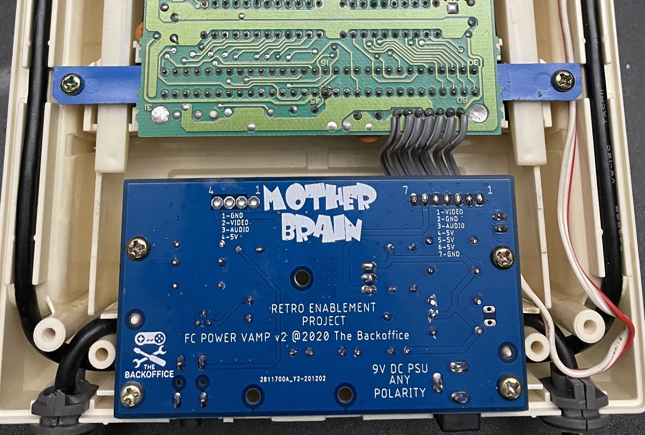
The FC Power Amp v2 from The Backoffice aims to be a completely no-cut solution that solves that by replacing the rear power board in the Famicom with a circuit that outputs composite video and audio via a 3.5mm jack. The circuit in this board also also has protection built in, reducing the chance of people connecting the wrong PSU and frying their Famicom! I still recommend using a brand new “Genesis 1 style” Triad PSU, just to be safe though.
Let’s take a look at the board and how it works.
Famicom AV Replacement Board: https://backofficeshow.com/shop/famicom-psu-av-replacement-board
Triad PSU: https://www.retrorgb.com/quality-psus-for-classic-consoles.html
RetroTINK: https://www.retrorgb.com/retrotink2x.html
I wanted to setup before and after tests of this board and used my original Famicom to test. That console was gifted to me awhile back and already had a composite mod built in, so it should be a pretty fair comparison. To start, I used a basic thermal probe kit and taped two probes inside using Kapton tape: One directly on the voltage regulator and the other near it to test ambient temperature.
DISCLAIMER: The thermal tests I performed in this review are by no means “extensive”. They provide a basic idea of temperature and while they’re certainly more accurate than other methods, there are always other factors that could affect your setup! I’m also using a brand new, well-performing Triad external AC-DC power supply and I’m sure that will affect these results as well. Basically, your results may vary!!
The area I chose for ambient temperature readings was next to the power board, but still in an spot with a bit of space for airflow. If I had access to the equipment I used in former companies while doing computer hardware design, I’d also put probes on the CPU, PPU and in multiple ambient areas, but this test should at least warn us of any extreme temperature spikes.
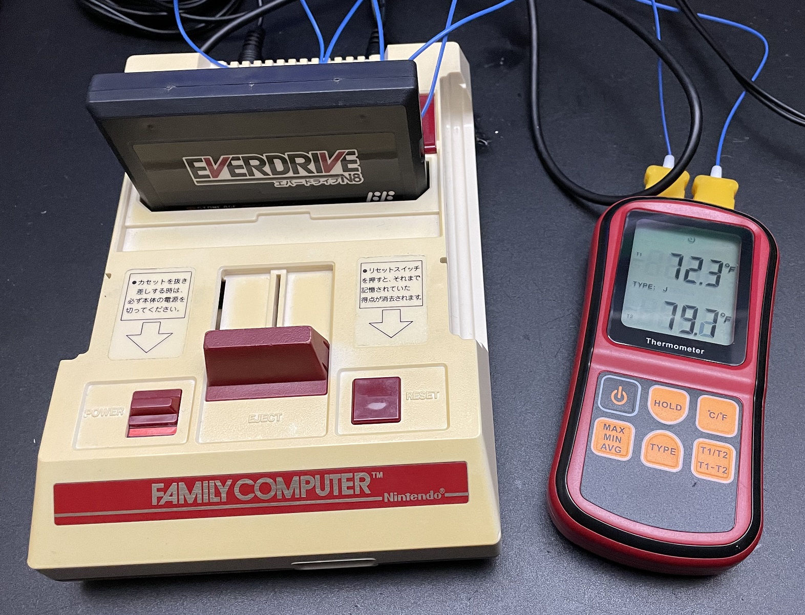
Right after powering on, the temperature showed 86 degrees Fahrenheit on the 7805 power chip and 80 degrees on the ambient probe.
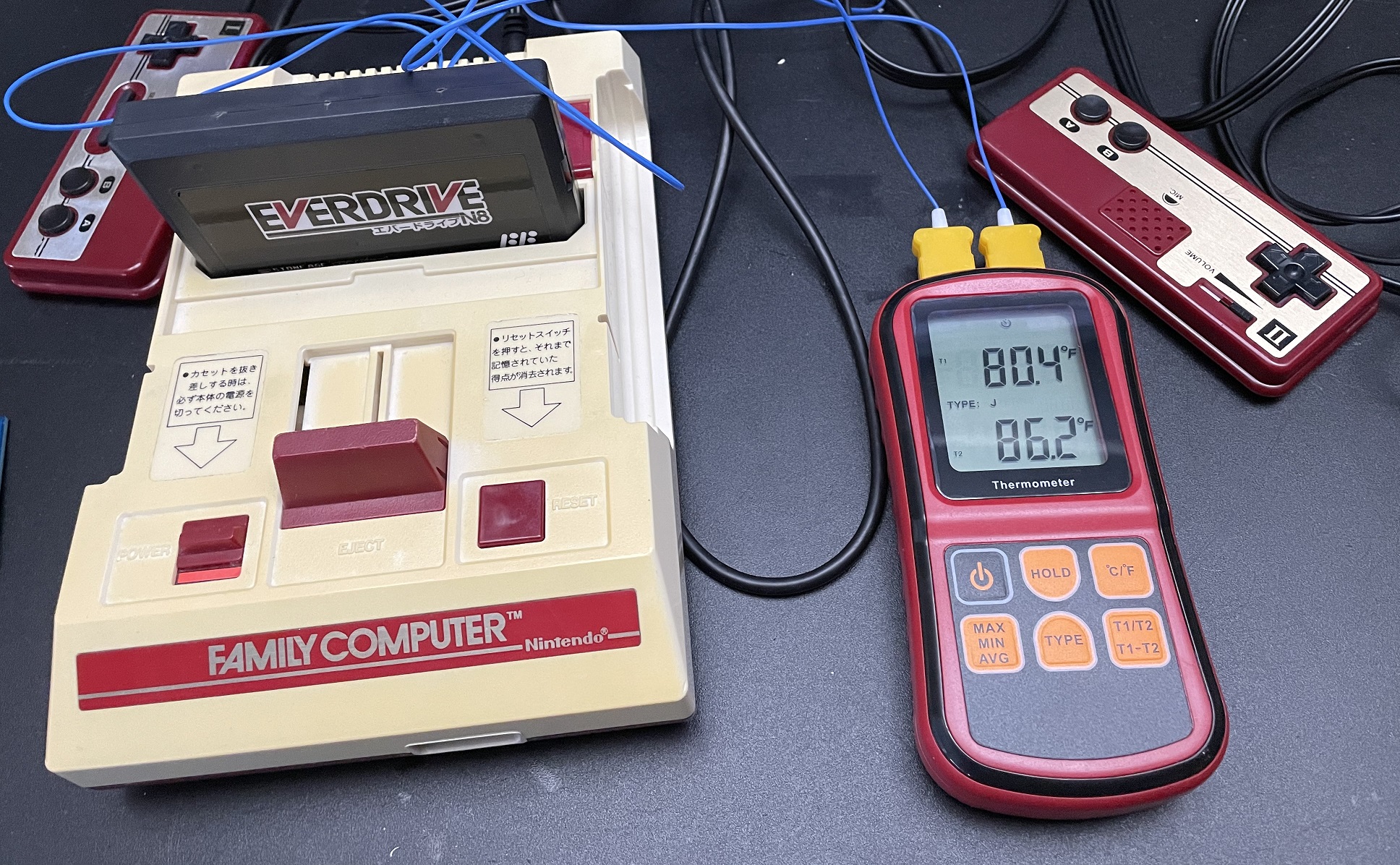
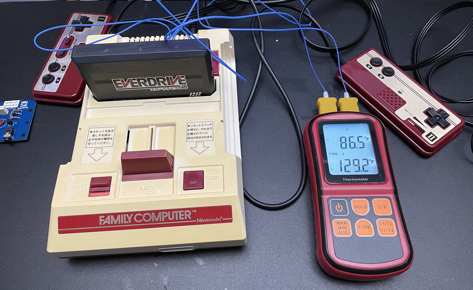
After 30 minutes of letting the Super Mario Bros. 3 title screen run in a loop, the results of the original Famicom power circuit showed around 86 degrees ambient and 129 degrees on the 7805. I took a screenshot using the RetroTINK 2x Pro at this point for a “before” capture – More on that later.
Now that we have our baseline reading, it was time to install the new board.
PLEASE NOTE: If your Famicom’s motherboard revision doesn’t match this one (specifically the GPM-02), installation will be different. The video embedded on the bottom of this page shows an alternate installation method.
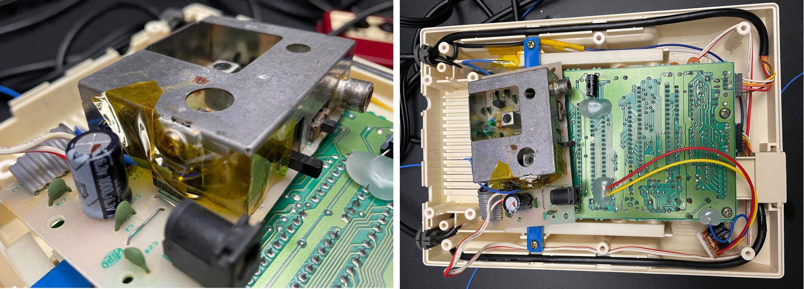
First, I had to remove the existing composite video mod, as well as the globs of glue holding it in. Some isopropyl and a Q-Tip were able to get the glue un-stuck pretty quickly and it came right off with tweezers:

I also had to de-solder the ribbon cable and the power switch cable from the original board as well. The ribbon cable was the only part that might be tricky for beginners; I chose to use a desoldering gun which many people might not own. You could probably get away with snipping the ribbon cable wires as close to the old board as possible, then re-stripping, however the ribbon cable is extremely short and it might make connecting the new board harder:
When reassembling, the orientation of the switch wire doesn’t matter. Also, the ribbon cable lined up intuitively, but I always recommend double checking with a multimeter; The pins are labeled and it’s easy to check the orientation based on which pins are ground:
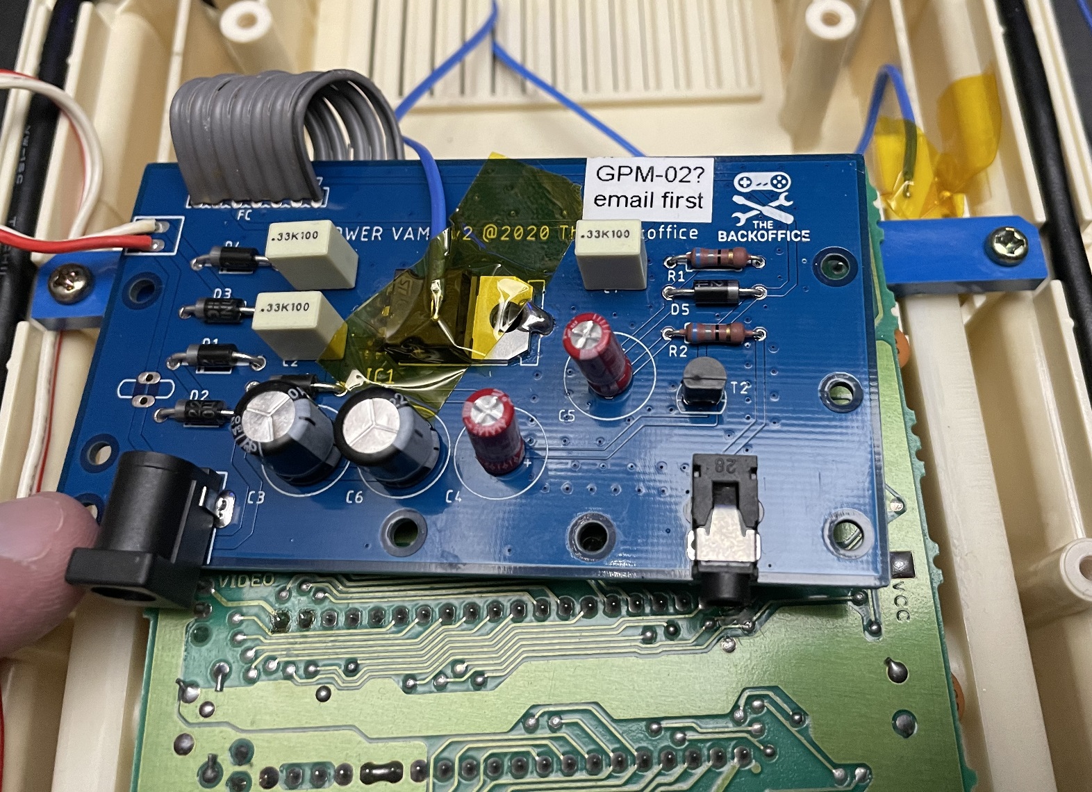
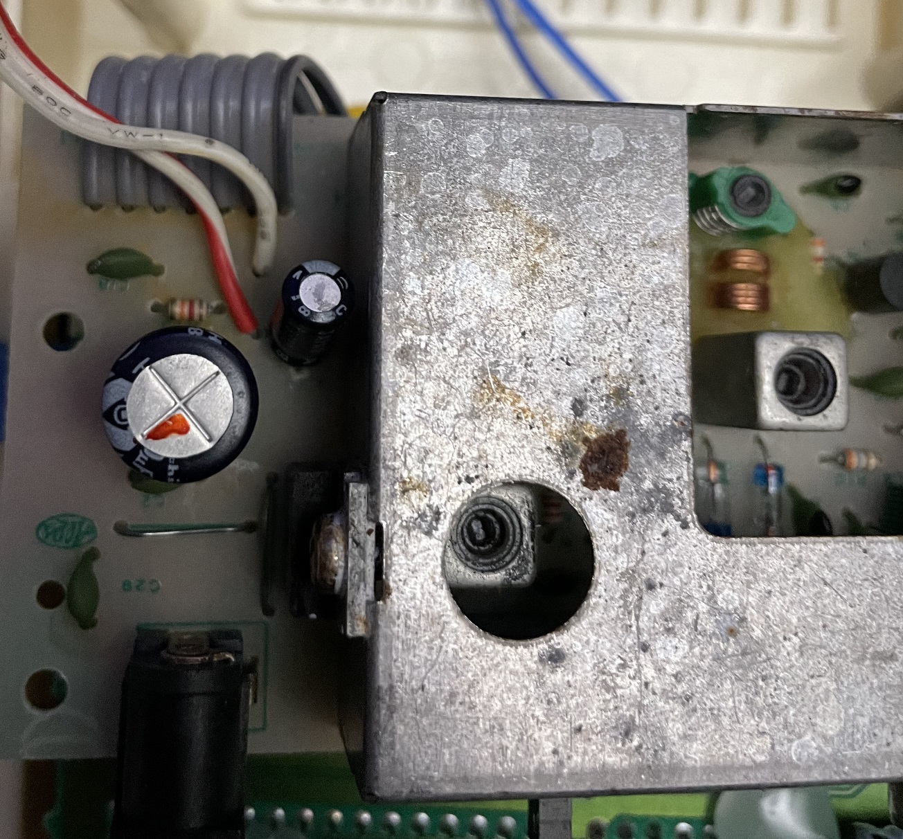
After the wires were re-connected, I taped another probe directly to the new voltage regulator. The ambient probe was still in the same place as before as well. After putting it together, I took another “cold” reading and it showed about 79 degrees Fahrenheit on the voltage regulator and 72 degrees ambient. This makes sense, as I’d cracked the window next to me when soldering and the room temperature went down a bit.
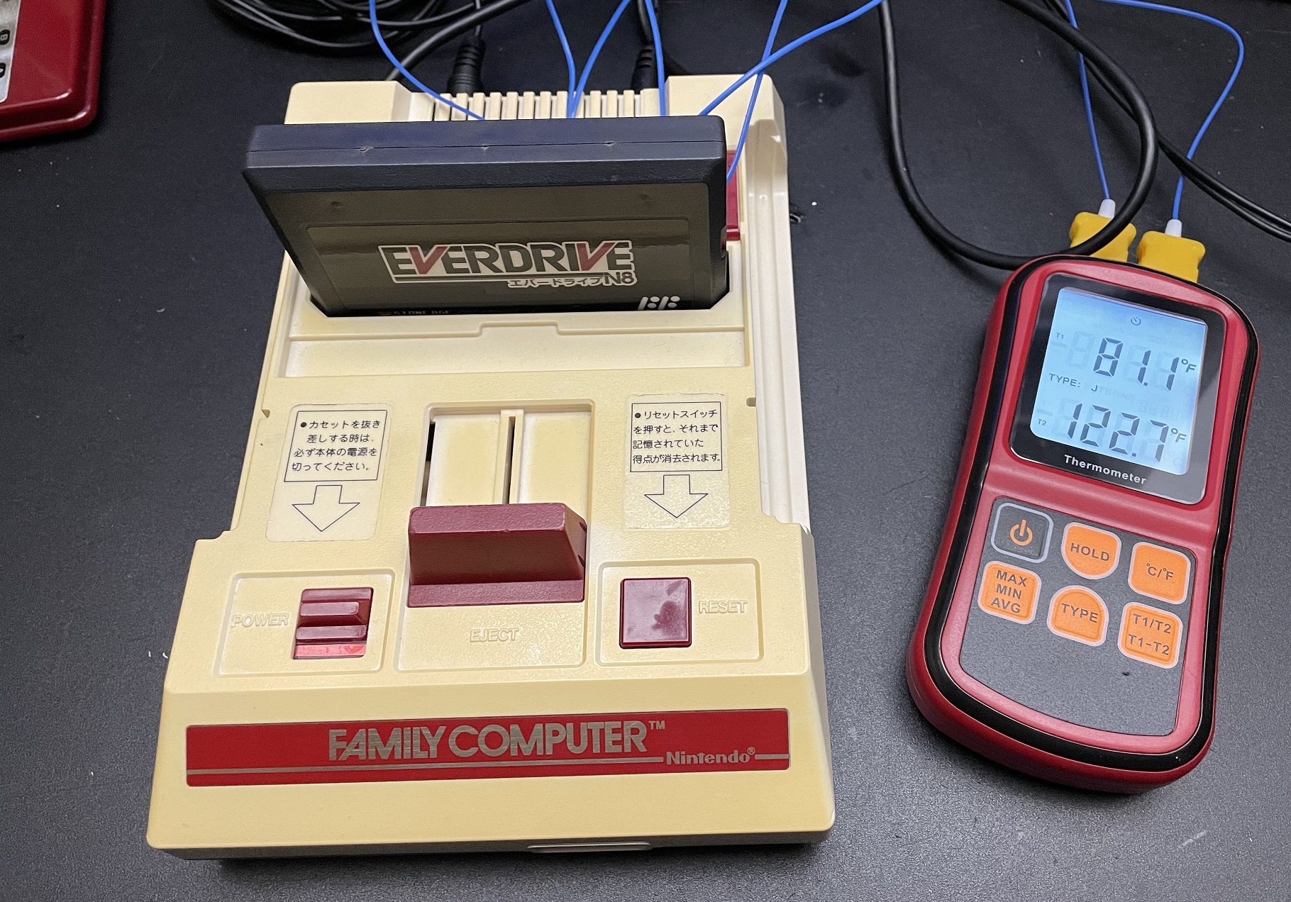
I closed the window next to me and once again let the console sit at the SMB3 title screen for about 30 minutes. When I came back, it showed about 123 degrees Fahrenheit on the voltage regulator and 81 degrees ambient. If you consider the room itself was a bit colder than before, it seems the new power board performed exactly like the original. I absolutely NEED to once again point out that I was using a new Triad power supply and using basic test methods – I’d expect very different results if a different (especially a low quality) PSU was used for this test and the console was in a heat chamber!!!
Here’s the results of the before and after RetroTINK capture (click for full-sized). PLEASE NOTE that the terrible jailbars you see here have nothing to do with this mod! They’re quite commonly found on original Famicoms and I’ll soon be researching ways to clear them up, so please keep an eye out for those posts!
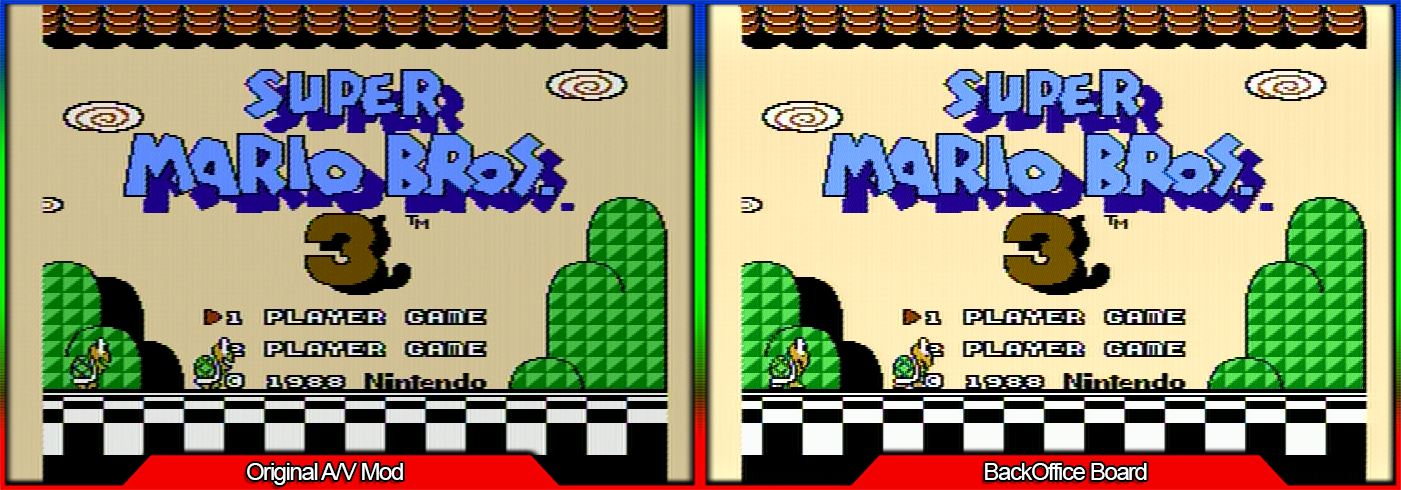
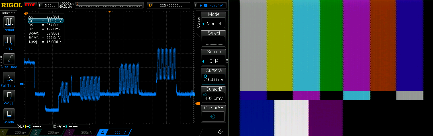
As you can see, the output is definitely brighter than the original mod whoever had the console before me installed. I wanted to verify it wasn’t too bright and used the 240p test suite’s white screen and color bar screen to verify: It’s definitely well within the voltage limits and should be 100% safe to use, even considering analog video voltage tolerances you’ll see between each motherboard:
With the tests done, I removed the thermal probes and bolted everything back in place:
The orientation of the power jack seems perfect, but I do hope they find a way to slightly raise the 3.5mm jack used for video and mono audio. To be clear: This is still a 100%, completely reversible #nocutmod and the new AV jack fits fine…I’d just like to see it a bit more centered vertically.

Maybe the seller will consider a “pro” version of this some day, with more features implemented. Since there are now holes where the TV/Game and channel switches used to be, there’s certainly room to grow: Maybe there could be an audio circuit with a small POT sticking out one of the holes that can blend the channels into “fake stereo”; An often-misunderstood method of separating the console’s sound channels. While my personal opinion is that 100% separation of these channels sounds weird, having just 10% or 15% separation provides a “depth” to the audio I quite enjoy. Having a POT that adjusts this between full mono and full separation would allow people to decide for themselves.
Also, since each of these consoles might output slightly different voltages, maybe the second hole could be used to adjust the brightness output? I think with the right POT, you should be able to adjust between completely safe levels, that could compensate for any board differences.
Either way, in it’s current form, this seems to be a decent solution for original Famicom owners who want a clean composite video output solution.
Here’s another review of this board that also shows another installation method: