SNES Mini SPDIF Digital Audio Installation
This page shows how to install a digital audio board into a SNES Mini. As an FYI: To permanently mount the board, you must cut a hole in the plastic of your SNES.
As an FYI, there are two types of audio that are not compatible with the digital audio mod:
– Super Game Boy adapters create their own audio, so Game Boy audio can only be passed through the analog-out of the SNES, not digital.
– Any homebrew game that uses the MSU Audio programming of the SD2SNES rom cart will not work with the digital audio mod. All other games work and sound perfectly via the SD2SNES, but (much like the SGB), MSU audio is created in the SD2SNES cart, not the SNES, bypassing the internal sound chips.
Other then that, as far as I know, there are no other game compatibility problems, but PLEASE NOTE: This digital audio mod is not compatible with many stereo receivers. I’ve been lucky and have had great success, however many other people have problems with their setups.
Tools / Parts Needed:
You’ll need a few tools for this mod (more info on the tools can be found in the tools section):
– SNES Digital Audio board
– Basic soldering skills.
– The 4.5mm tool that opens the SNES
– Philips head screwdriver
– Soldering iron / solder
– Thin gauge wire
– Sharp cutting tool, such as an x-acto knife or razor
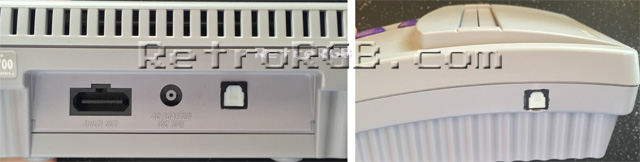
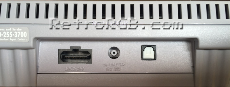
Before starting, you should choose a location for the digital audio board. I prefer to use the area next to the multi-out (above-left), but I’ve found mounting it on the side (above-right) works really well in some situations, depending on how you need to run your wires. This guide shows how to mount it in back, as that seems to be the most common place people would want it. Also, if you’re unsure about cutting the plastic, you could always run the wires through the rear vent holes. It’s ugly, but it’s a good way to test before making a permanent modification to your system.
Start by completely disassembling the SNES Mini, including the removal of the metal heatsink (please ignore the wire in this pic; It’s the csync wire from the RGB mod):
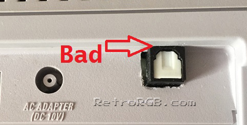
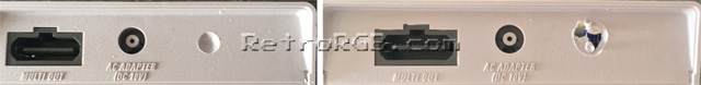
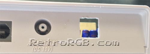
Next, choose your mounting location and start cutting a hole. If you choose the rear A/V port like I did, make sure not to drill the hole too high (as shown below), otherwise the optical audio cable won’t fit!!! Also, you can’t mount it too low, or the board will interfere with the capacitors on the motherboard (as shown in the pic above). The best height is shown two pictures below (the empty square).
You can cut the hole with a knife, but I found an easy way to get started is by drilling a hole. I usually start by using a small drill bit (around 1/4″), just to make an impression in the plastic. Then, using that impression as a guide, I chose a drill bit that’s just smaller then the SPDIF port (around 3/8″) to make the initial hole. You’ll want a snug fit for the connector, so make sure to not use a drill bit larger then the connector.
Then, use a razor or x-acto knife to cut the hole into a square. I found that using a file helps as well. Once again, you’ll want it very snug around the connector.
Next, cover the bottom of the digital audio board in non-conductive tape. You must not forget this step, as the board will touch some of the capacitors on the motherboard and could potentially cause a short!!! Then, apply a bit of super glue or epoxy around the inner connection between the digital audio board and the SNES plastic (as shown by the arrow) Click for full-sized:

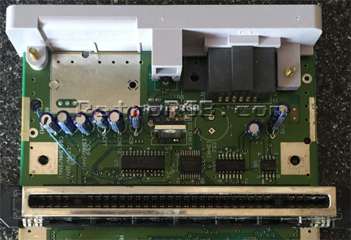
Then, locate the following points on the bottom of the motherboard and solder a wire to each one (I suggest using the full-sized picture below this one as a reference as well). Also, make sure not to forget #5, which is towards the bottom and shown in the right pic (click for full-sized):

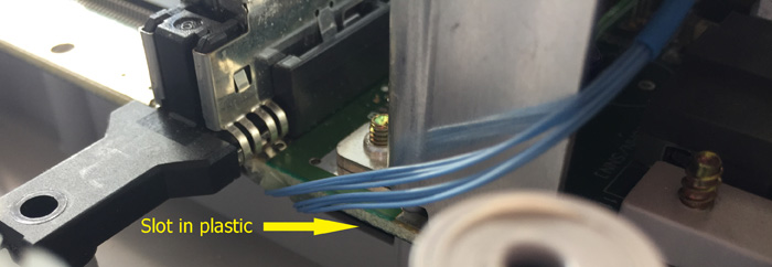
After soldering the wires, run them along side the board. I suggest using the exact spot I did, to avoid pinching the wires in the SNES’ plastic. Here’s some tips for making this a bit easier (click the pic for full-sized, RGB Amp also shown in the full pic):
– Put a tiny dab of hot glue on the board, then push the wires into it before it cools. I found it easier to use two dabs / two groups of wires This close-up is deceiving and makes it look bigger then it is; You’ll notice the two tiny bits of glue are even smaller then the screw head in the picture.
-Hold the #5 wire in place with a bit of tape, just until the glue dries. You can remove the tape after you’re done, it’s just there to keep the #5 wire from moving around.

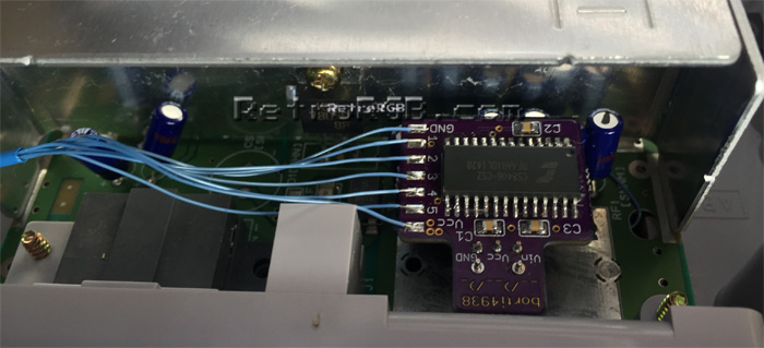
After putting the board back into the bottom plastic, it should look like this:
Next, cut all the wires to size and solder the numbers from the mounting points (listed above) to the corresponding pins on the digital audio board. Then replace the heat shield:
That’s it! Now you can enjoy digital audio from a SNES!
If you’re done, feel free to go back to the main SNES page. If you’d like info on mods for other systems, head to the Getting RGB From Each System page or check out the main page for more retro-awesomeness.