la·ten·cy [ˈlātənsē] – the delay before a transfer of data begins following an instruction for its transfer. – oxford dictionary.
Modern gaming systems take into account the various inherent latencies and specifically code games within those limits to give us gamers an enjoyable experience. The systems often output at the TVs native resolution, reducing the latencies introduced by any up-conversion of the video resolution or they employ custom radio transmission protocols in their controllers to reduce the lag. The games are coded in such away to make the delays in button presses seem less noticeable. However, Latency, also known as Lag or Delay, is a bane of retro gaming on modern Audio/Visual Systems. The game consoles of old worked with CRTs, which had the latency of whatever distance the wire was from the console to the tv divided by the speed of light and the same for its wired controllers. Its true that some games introduced some delay in their processing of the data in from the controller, but overall the entire system had very little lag. With modern equipment and modern conveniences, latency is felt much more. Things can seem “sluggish.”
A while back on SmokeMonster’s Discord, people were trying to figure out the best way to test the latencies introduced by the new wireless controllers for their retro gaming systems. Some were using the lag test in the 240p gaming suite, or using a high-speed camera to capture when the character on screen reacted. And while there are good tests, they test the entire system, controller, game, TV while also introducing a human variability into the equation. Being an engineer by day and a retro gamer, I decided to do a quick test for those interested. We will explain the steps to setup the test so anyone with the want, some “Industry Standard Lag Testing Equipment”, a.k.a. an oscilloscope, and a cheap multimeter can reproduce the setup and run the tests at home.
This article will not be an exhaustive explanation of how to test controller latency on every type of controller on every system. It is testing perhaps the simplest case possible. The methods explained here can be adjusted an expanded upon to test most cases. Sometimes additional hardware will be required due to the nature of how the original systems read controller data, but the basic principles will apply.
How does a controller work? Internally most controllers on the oldest of gaming systems were very simple electrically. They were simple switches that applied, or didn’t apply voltage to a line, not to terribly different from the light switch on your wall. Luckily for me, the controllers on the Sega Genesis were designed to be compatible with those older systems. Below is a simple schematic, showing how the old controllers are wired. When the button is not pressed voltage flows from the power supply, the ‘1’, down the wire and to the system. The system then sees a ‘1’ at its inputs. When the button is pressed, the voltage at the system is seen as a ‘0’

Wireless controllers work similar. There will be a circuit line the one shown on the controller itself. When the button is not pressed, the processor in the controller sees ‘1’ and it sees ‘0’ when the button is pressed. The processor sees the line change state then sends the data via a radio transmitter. The receiver picks up the signal and passes the information to the processor located in the receiver. That processor will then “pull” the appropriate signal on the console to a ‘1’ or ‘0’, depending on the data received.
Now that the electrical lesson is out of the way, lets look at a specific example, the Sega Genesis. The controller port of the Genesis has the following signals that we are interested in. Power, +5V, is supplied by the consoles. This is the ‘1’ in the schematic. GND is connected into the ground of the console and is the ‘0’ in the schematic. Left is the signal going from the controller to the system. As shown in the schematic, Left will be at ‘1’ until the button is pressed. Then it will drop to ‘0’. With a wired control, the signal transitions from ‘1’ to ‘0’ near instantly. With a wireless controller, there is data processing, transmission, more processing and finally the signal will drop.

For testing the latency, we are going to need some equipment in addition to the controller.
- A Genesis or a Genesis Analog.
- A multimeter
- An oscilloscope.
And that’s it for the industry standard testing equipment. The easiest way to test is by using a stock Genesis with no game inserted. Not having a game is very important due to how the Genesis reads buttons. There is a select signal output from the genesis that remaps the signals to different buttons. If there is no game inserted, the Genesis leaves this signal at ‘1’, and Left stays mapped to Left. The alternative is to construct a cable shown below, connecting a 5V supply and GND to the correct lines.

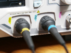
For our example, we will use a Genesis and connect the blue probe to it. The color of the probe doesn’t matter I just like keeping it consistent with the display of the scope.
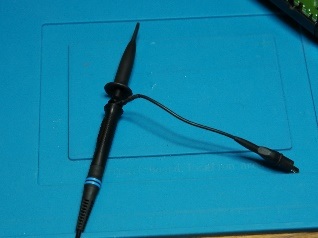
Using the spring clip on the probe, hook the middle wire on the back of the controller port. Connect the alligator clip to anywhere on the system shielding to ensure a good ground signal for the probe.

The setup for the controller is a little more involved. We need to find the Left signal and the GND on the PCB for the controller. This is where the multimeter comes into play. We will use the ohm measurement to try to find the GND signal.
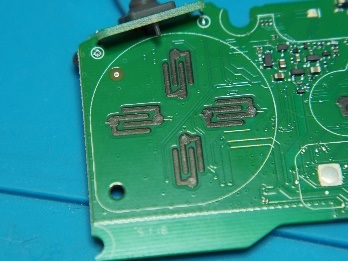
In the photo, you can see the pads for each of the buttons for the D-Pad. If you look closely, you will notice that there are actually two different pads under each button. From the schematic, we know one of these is ground and one of these is the signal for the button.
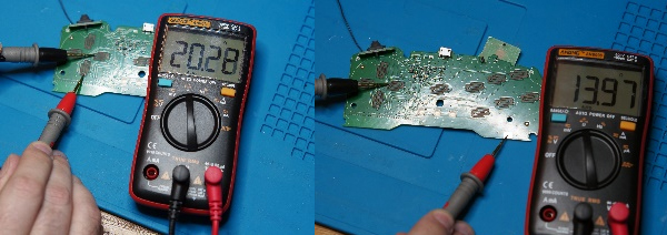
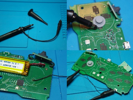
The GND on every button is connected together, with this knowledge we can probe around until we find two pads that are connected together by very low resistance, say less than 30 ohms. Once we have found ground for the pad, we need to find a good point to connect the ground to our probe. The M30 has a nice spot to clip to in the bottom right-hand corner. We have a couple choices for connecting the probe to the left signal, if the controller has a very large pinned processor, you could trace the signal from the left button to the pin on the processor and hook the probe. If the pins are smaller, you could try to use a test lead to hook the pin.

Failing those options, you could remove the hook from the probe, or more extreme, expose a trace and solder a wire to the trace to hook. Since I was testing multiple controllers several times, I personally opted for using clips on the Joyzz and soldering wires on the M30s. Once we have the controller connected to the probe, we are ready to setup the oscilloscope.
I used the Rigol 1054z for the initial set of tests conducted. It is a decent scope and fairly affordable. Here are the steps to setup the test.

• Connect the probes to CH1 and CH2 on the scope and power it on.
• Press the CH1 and CH2 buttons on the face of the scope until both channels are lit.

• If you don’t see any signal on the display, press the mode button in the trigger section until Auto is lit.
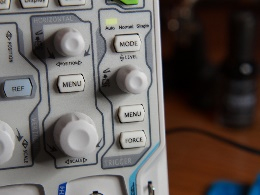
• For each of the channels, press the CH button and adjust the scales. I use 1V on CH1 and 2V on CH2. Plug in the receiver to the console and turn on the console and controller. You should have an output similar to this.
• Pres the Menu button under the trigger section. Set it to trigger on CH1 and adjust the trigger level to be some where around 2V. Press and hold a button. If everything is hooked up correctly, you will have a display that looks like the following.
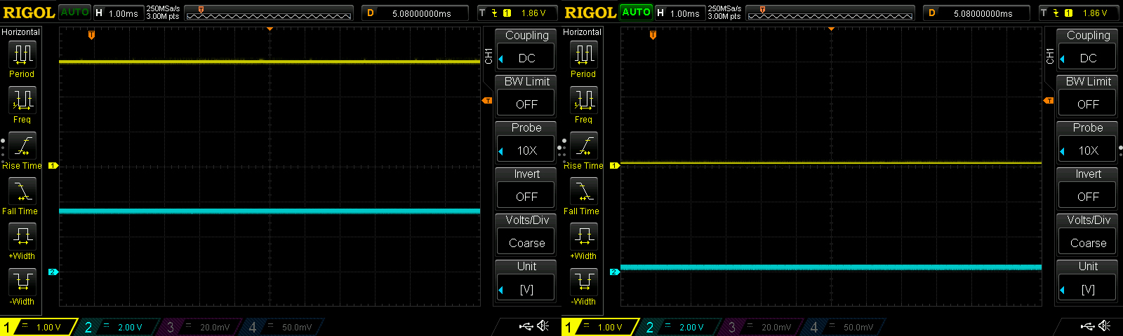
Notice that the voltage for both signals is 0. When you release the buttons they will both rise again.
• Next press the mode button, under trigger until Normal is lit. This will cause the scope to capture an event when the trigger conditions are met. Press the Left button on the controller and the scope will capture the transition. You can play with the position dial under the Horizontal section to get the trigger to be on the left-hand side of the display and then adjust the scale until you see the transition on CH1 and on CH2 on the display at the same time. Just keep adjusting setting and pressing the button until the display looks how you want it.
• Zoom the horizontal scale to around 5ms. Depending on the measurement, it might be better at 1ms or 10, but 5ms is a good place to start.

• Next press the measure button under Menu.

• On the right-hand side of the display, press the down arrow until Setting is shown on the display and press the button next to setting. Change the Type to Delay and Source A to CH1 and Source B to CH2.

• Press the Menu button on the left-hand side of the display until it shows the Horizontal options, and then the down arrow until an option Delay. Press the button for the Negative Edge Delay. This is where the signals start high and drop low.

• This will cause a box to show up on the screen. When you cause a trigger, you will get a display like this. The value in the box is the time between CH1 dropping and CH2 dropping and is the latency measurement for the controller.

And there you have it. Now you have the know how to test whether a claim of Zero lag is truly 0 or if its just marketing. Things to consider, all of the wireless controllers run in the 2.4GHz spectrum. Other things can interfere with the transmission and cause additional delay. For perfect testing, you would test in an EMI chamber. This would remove all outside radio interference. However, we don’t play our systems under such conditions. Be mindful of what things running on 2.4GHz when measuring, it could affect you results, especially microwaves. Microwaves work at 2.4GHz since water absorbs and heats up at that frequency. When taking apart you controllers, look for the antenna. It will be a trace that looks like a square wave. See where that is in relation to where your hand would be. If your hand would cover it while playing, your latency would increase since you are 70% water. One final though before leaving, always test claims from manufacturers or ask for the data backing them up. “In God we trust. Everyone else gets to provide data.”
-Enforcer