Sync Stripper
This page provides information on the Sync-in-SCART board, originally designed by Alex a.k.a. ArcadeTV. This board can be installed anywhere an LM1881 sync stripper is needed, but I provide detailed instructions on installing it into a SCART head. PLEASE NOTE: You do not need a sync stripper for SCART equipment!!! A board like this could be used inside SCART to BNC cables, for things like converting a SCART cable for use with a BNC Extron Crosspoint switch, or a video production monitor that requires TTL sync. Do not use them if you’re connecting the cable to a SCART device!

Current Sellers:
SNYC-IN-SCART Board, US Seller
SNYC-IN-SCART Board, UK Seller
Parts Needed for DIY:
– The Sync-in-SCART board
– Basic tools, such as pliers, tweezers, etc.
– Soldering iron / solder
– Thin wire
– Basic soldering skills.
– One 470 ohm, 1/4 watt resistor (DEFINTELY recommended in SCART applications)
Installation:
This board can be installed anywhere you need to “strip” csync from either composite video or luma. For installation inside a console, simply solder (from right to left as shown above) ground, composite video (or luma), 5v power and finally csync output. If mounting inside a console, I suggest either using heat shrink tubing to cover the contacts and ensure nothing can touch it, causing a short.
– First, start by adding solder to the 4 pads on the sync-in-SCART board. Simply touch the tip of your soldering iron to each pad, then touch the other side of the pad with the solder and hold until the solder spreads across:

– Next, open the SCART connector and find the row of pins we’ll be working with; We’ll only be using the longer “top” side. Also, if your SCART cable came with hot glue covering the pins, carefully remove it before proceeding:

– Now it’s time to add wires to the SCART connector.
– First, de-solder the composite video wire that’s in pin 20 (the right-most pin on the connector below) and solder a short wire in its place.
– After that, use a multimeter to double check for voltage and solder a wire to that pin as well; 5v power should be coming from pin 8 (4th from the left in the pic below).
– Finally, use a multimeter to find any ground pin and solder a short wire to it. This connector had a separate ground pin that was located just in front of the other pins, making it very easy.

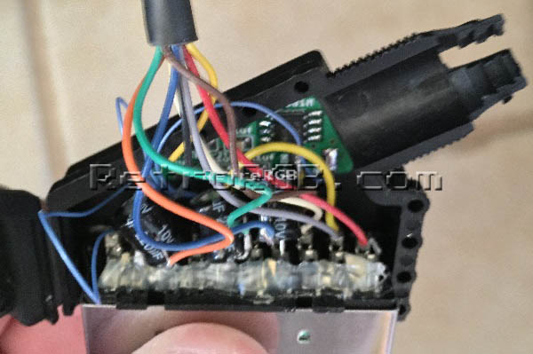
– Now add either double-sided tape or glue to the back of the Sync-in-SCART board and affix it to the inside of the SCART connector:

– Next solder all the wires to their corresponding places on the board.
– CS-OUT goes to pin 20 on the SCART connector, the same pin you removed the original composite video wire.
– 5v should connect to the wire you added to pin 8.
– V-IN should be connector to the wire that was originally connected to SCART pin 20.
– GND should be connected to any ground point.

– Finally, carefully re-assemble the SCART connector and make sure no wires get pinched. I found that there was plenty of space inside, but if you’re concerned about the Sync-in-SCART board touching anything, feel free to cover it with a piece of non-conductive tape.
That’s it! A pretty simple installation that’s extremely useful when your setup requires csync, but your system only outputs composite-video-as-sync.
75 Ohm csync output
As stated at the top of this page, this device is designed to output TTL-level sync to non–SCART devices. If you need lower voltage csync (that you’ll find in SCART cables), then you’ll need to add one 470 ohm, 1/4 watt resistor to attenuate the output to 75 ohm video standards. If you’d like to be safe, just add solder the resistor to the csync output pin and see what happens. Using sync strippers should be expert-only and not for beginners!!!
Ifyou’ve arrived at this page as part of the RGB Guide, please move along to: what method you’d like to use to display RGB. If not, feel free to head to the main sync stripper page, or check out the homepage for everything else we have to offer.