SNES Mini S-RGB Expansion Board
This guide shows you how to enable RGB and S-Video output on a SNES Mini / Jr using its built-in RGB amp (the ‘S-RGB’ chip). This method requires a custom board that connects all the components. If you plan on using the S-RGB Encoder, this is definitely the method I recommend.
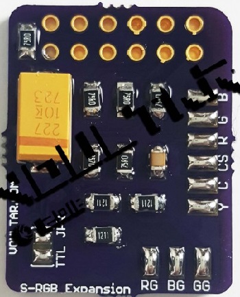
Parts required: Voultar’s Custom S-RGB Board
You’ll need a few tools for this mod (more info on the tools can be found in the tools section):
– The S-RGB connection board linked above
– Soldering skills!
– SNES RGB cable.
– The 4.5mm tool that opens the SNES
– Philips head screwdriver
– Soldering iron / solder
– Thin gauge wire
– Flux (or a flux pen) will make installation easier, but is not necessary.
RGB Cable / Sync:
This page describes the RGB SCART cables you’d want to use with this mod: SNES RGB SCART Cables
Installation Video:
This is a video demonstrating everything shown in this guide. It may help in your installation:
RGB Mod:
The mod is pretty easy, however soldering to the S-RGB chip can be extremely challenging. I usually recommend beginners use an amp bypass mod for ease of installation, however if you’re willing to solder to the small points this will work perfectly:
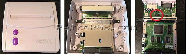
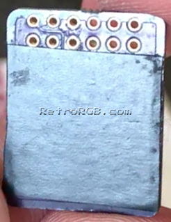
– Remove the 4 screws holding the plastic cover on using the 4.5mm tool. Then remove the 7 screws holding the motherboard in place (so, basically, just unbolt everything). Finally, unbolt the three screws holding the heatsink and find the S-RGB chip:
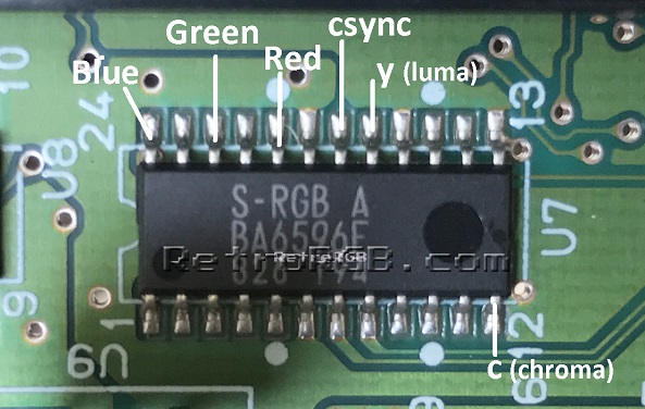
– Solder six wires to the pins on the “S-RGB A” chip as shown below. A few tips: These are extremely small pins and very difficult for people who aren’t experienced at soldering to work on. Use a soldering tip that’s extremely thin, as well as very thin solder. Make sure to “tin” each pin and each wire before trying to solder them together. I also like to add flux to each of the pins before tinning, as it makes soldering to them much easier:
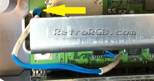
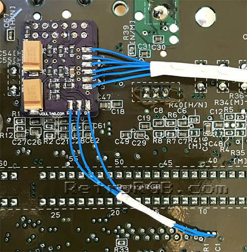
– I like to use heatshrink tubing to keep the wires together and also protect them from touching any other components. Then, I replace the heaksink and run the cables through the hole pictured below on the left:
– I suggest adding non-conductive tape to the bottom of the circuit board. Many boards don’t need this, however it’s my opinion that since it won’t hurt anything, better safe then sorry:
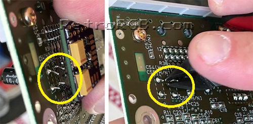
– Next, prepare to mount the circuit board over the multi-out pins. You may notice that there’s a few larger components sticking up. If so, it’s okay to snip them. Also, I’ve actually seen a few SNES Mini’s come from the factory with the two ground pins soldered together. If your system has this, you could either cut the solder in the middle (be really careful not to damage the pins), or use a solder-removing method (de-soldering iron, solder wick, etc):
:
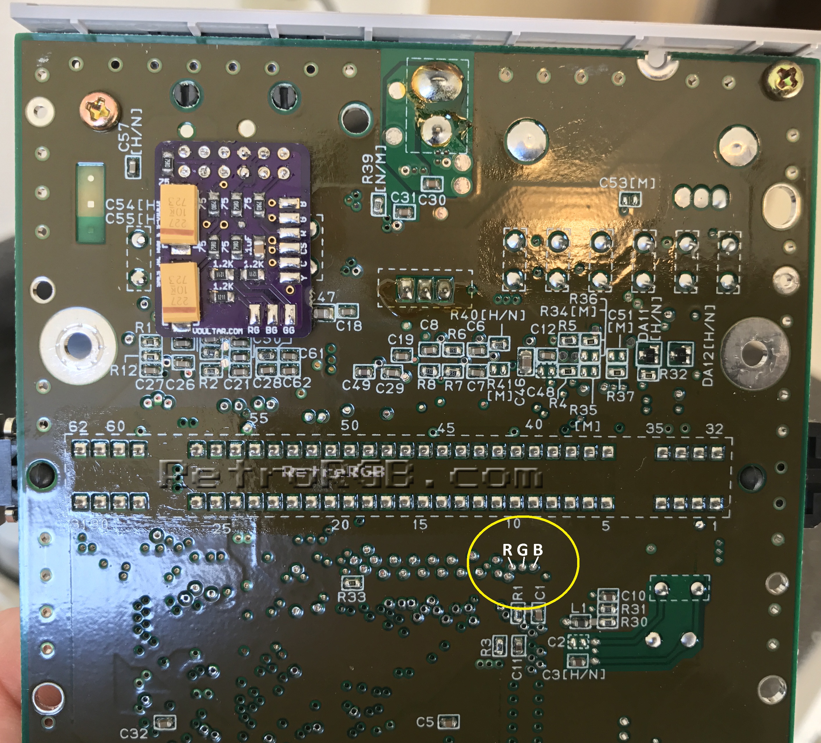
– Then, place the board over the multi-out connections and solder the multi-out pins to the board. Then solder wires from the bottom RGB pads to the via’s (holes) marked below – Flux will make soldering to those holes MUCH easier (click for full-sized):
– Finally, cut the RGBs / YC cables to size and solder them to the corresponding pins on the board. I prefer to use heat shrink tubing to keep them all in place:
– Then just bolt everything back together and give it a try!
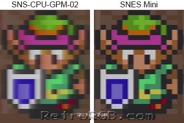
Results:
A pretty easy mod and the picture quality is amazing!!! Check out the difference from an average SNES 1 to a SNES Mini (there are many more pictures on the SNES Version Compare page):
When you’re done, feel free to go back to the main SNES page. If you’d like info on mods for other systems, head to the Getting RGB From Each System page or check out the main page for more retro-awesomeness.