The GunCon 3 was a gun peripheral made for the PlayStation 3 and developed by Namco. It worked by placing two IR emitters on top of your television that the gun would use to help track its position on the screen. The MiSTer FPGA project added support for the GunCon 3 so you can use it in any core that supports light guns. It’s a much more accurate solution than using a Wiimote.
Now if you’re planning on buying a GunCon 3 to use with your MiSTer setup, you will notice that complete sets can be very expensive. You can find the GunCon 3 on its own much cheaper, but the emitters are still required for it to work. A Wiimote sensor bar will NOT work and the emitters alone will also be quite expensive.
So, what’s another option? Well, you can buy the GunCon3 alone and build your own emitters. On the MiSTerFPGA discord there was a discussion on building them. Thanks to user awbacon on Discord, who also runs the Video Game Esoterica YouTube channel, we now know what we need to build these emitters. Here I will show you how to build these emitters, so you don’t have to spend a fortune on ebay. You can also check out my video at the top of this article showing the process.
So, here’s what’s needed.
- 6x 850nm IR LED emitters connected in series
- 2x 20ohm resistors
- A spare USB-A cable with one end cut off and exposing the black and red wires
- Plenty of wiring
- Soldering skills
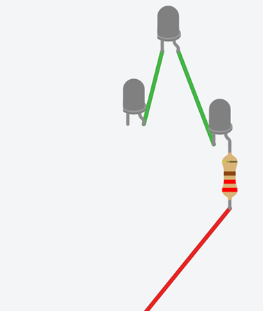
So after you have the components ready, let’s first solder the emitters together. We want to create 2 sets of 3 IR LEDs connected in series. Below is an image of that this means. The longer legs are the positive side and the shorter leg is the negative side.
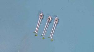
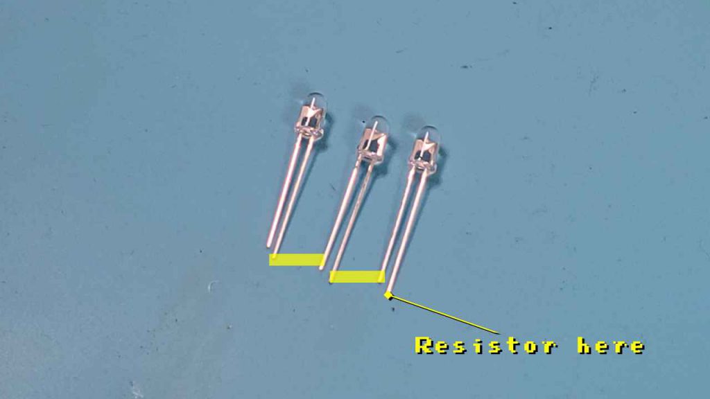
To connect these three LED’s together we want to solder the inside negative legs to the inside positive legs. The outside positive leg on the right also needs to have a resistor soldered to it. Like below.
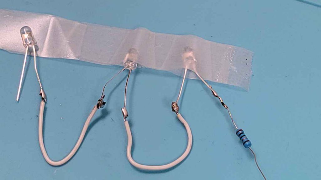
Instead of soldering the LED’s right to each other, I cut off some wires that gave me some spacing in case I needed to freely move the LED’s. Here’s what things should look like after you’re done soldering.
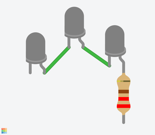
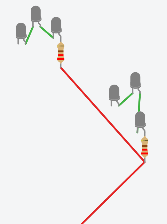
Here’s diagram also illustrating the setup.
You also want to solder a second set of 3 LED’s with a resistor. Once you have both set’s ready, let’s take one of them and solder a wire directly to the resistor on the LED set. I chose a red wire for this because this wire is going to be soldered to the red wire on a USB-A cable. The length of this wire should be several feet depending on where you are going to plug and power the LED set from.
Next let’s take another red wire. This one must be about the width of your television. Solder one end of this wire to the same resistor we soldered the previous wire. Then solder the other end to the other resistor on the second LED set.
The next step is to take another wire, and for this one I used a black, and solder the ends of the black wire to the free legs on the LED sets. The free legs are negative legs.
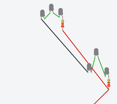
Now we want another black wire, this one should be the same length as the RED one that’s going to be soldered to the USB cable.
Solder this black wire to the negative leg of the LED set that has two wires soldered to the resistor. See the diagram below.
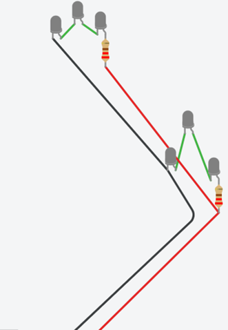
Finally, we want to solder the ends of the black and red wires that are free to the black and red wires of a cut USB-A cable. You’re done with the build after this. Check out the final TinkerCAD diagram.
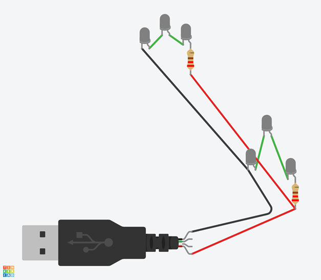
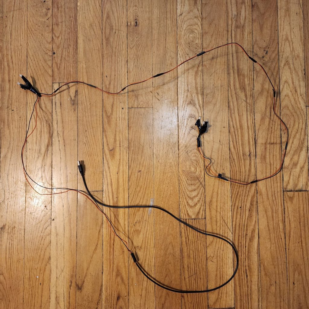
To organize things a bit better, you will want to wrap the LED legs up with electrical tape so they don’t touch each other. I also taped the cable’s together so there’s not a mess a of wires everywhere. Here is how my final LED set looks like.

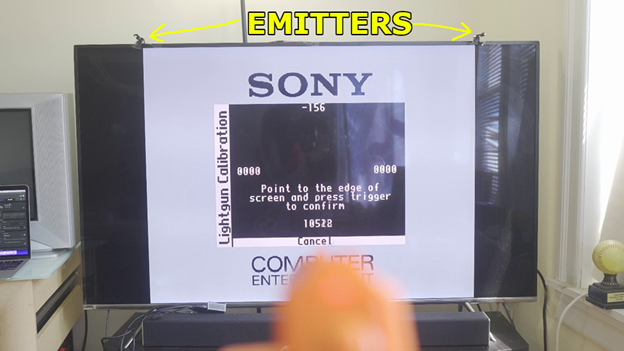
You can now place these emitters on top of your Television and plug them in to a free USB port on your television or use a USB power adapter.
The emitters should not be place on the top corners of the television, they should be place in the top corner of the games viewing area.
Configuring MiSTer and the PSX Core
The next step is to set up the emitters in MiSTer. A keyboard will be required.
Plug in the GunCon 3 to your MiSTer and turn it on.
We want to configure buttons on the Main MiSTer software and buttons for the PSX core.
For the Main MiSTer software go to “Define joystick buttons.”
Here you can assign the buttons on the GunCon 3. You can assign things the way you want. Here are my assignments.
- MiSTer Dpad –> GunCon3 Joystick A
- MiSTer A button –> GunCon3 B1
- MiSTer B button –> GunCon3 B2
- MiSTer X button –> GunCon3 Trigger
- MiSTer Menu –> GunCon3 C1
- MiSTer Menu OK –> GunCon3 Trigger
- MiSTer Menu Back –> GunCon3 B2
Next, let’s configure the PSX core. The original GunCon only has 3 buttons. The trigger and A & B buttons. Load up the core and go to “Define PSX buttons.” Here’s how I define my buttons, but you can always define them any other way you prefer.
- Circle (Trigger on GunCon1) –> GunCon3 Trigger
- Cross (B on GunCon1) –> GunCon3 B2
- Start (A on GunCon1) –> GunCon3 B1
Calibrating Gun
To calibrate the GunCon3 we want to use the area that’s only used for gameplay and ignore any black borders on the sides. To help us do this first enable “Pause when OSD open.”
- PSX Core Menu
- Miscellaneous
- Pause when OSD open = On
Enabling this will help freeze a screen that shows us the bounds we need to calibrate to.
Reboot the core.
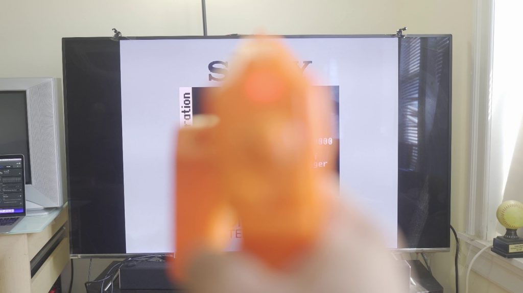
When the PSX BIOS boots up bring up the cores menu while the white background is still showing. Your display should like the screen below. You see the MiSTer menu, the gray/white background and the black borders. Had we not set the “Pause when OSD option” the core would continue executing, but now it’s just paused.
If you miss the white background just restart the core.
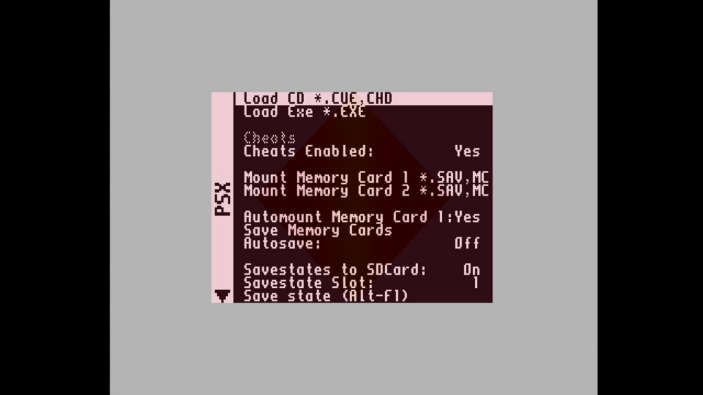
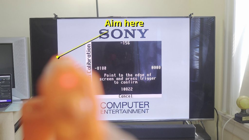
So while the MiSTer menu is still up, bring up the calibration screen by hitting F10 on your keyboard. You’ll see the below screen.
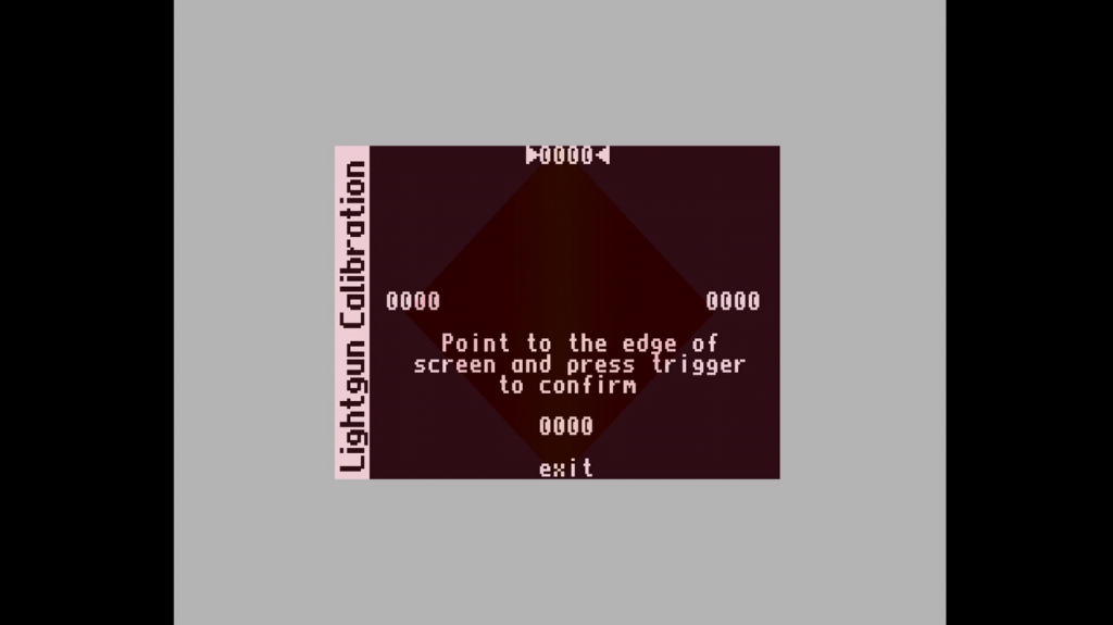
See the arrows point at the top number, this means to point the guncon3 to the top middle of the screen and hit the trigger.
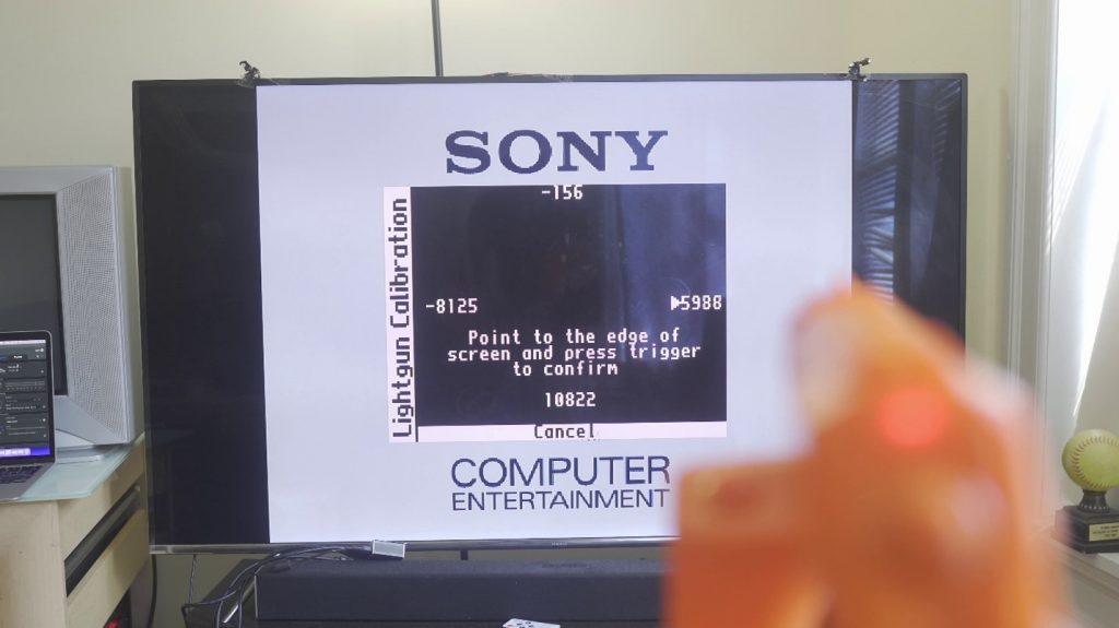
The arrows will now move to the bottom number, now point the GunCon3 to the bottom middle of the screen and hit the trigger.
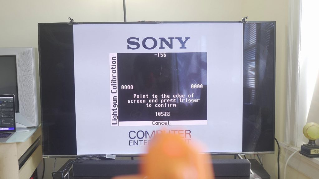
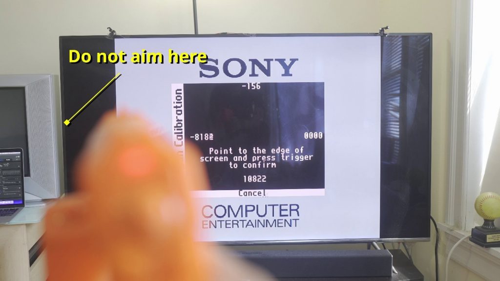
The arrows will now move to the left number. Here’s where the white background comes in useful. Point the GunCon3 to the left middle of the white background. Not the side of the television. Pull the trigger to move on.
Finally, point the GunCon3 to the right middle of the white background and pull the trigger.
After pulling the trigger, the core will then resume executing.
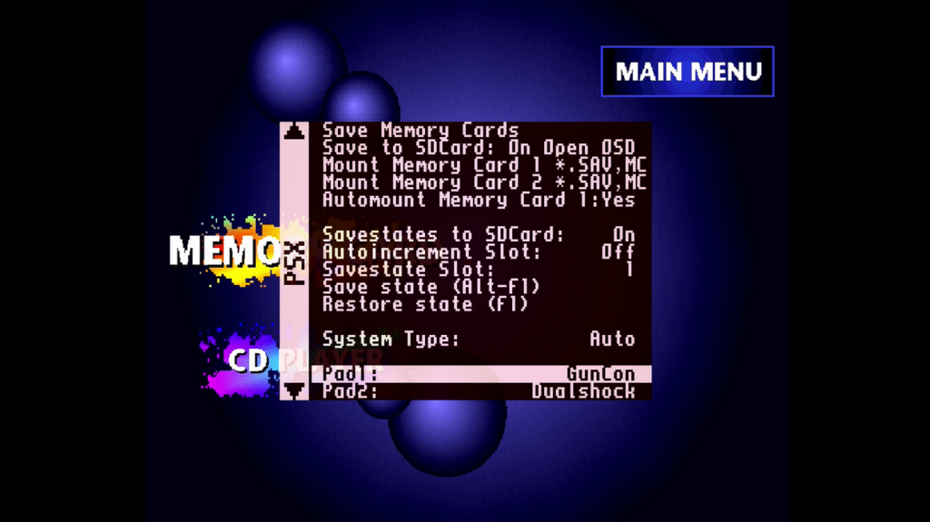
You also need to enable GunCon or Justifier mode on the core, depending on the game you want play. If a game doesn’t work for one mode, just try the other.
- Bring up core menu
- On Pad1 or Pad2 set it to GunCon or Justifier.
Now you’re all set! Just load up a lightgun game and start playing.
Things to note
Here are some important things to note to get the best experience with the light gun.
The physical location where you calibrate from is where you should play from. Moving to a different location will affect the accuracy.
The bigger your TV, the further back you have to stand so the emitters can be seen by the GunCon3.
Some games work better than others. I find Justifier support to be very buggy and in some games I couldn’t reload.
You will need to calibrate the gun for each core individually. You need to load the core and then open the calibration menu (F11). Calibration menu will only appear if the core’s menu is showing.
To configure buttons for other cores, check out my video showing how to do it for the wiimote. It’s the exact same process.
Enjoy!
Links:
- Defining buttons for other cores (it’s a Wiimote video but the process is the same): https://youtu.be/WBoZDGn0e3U?t=154
- Video Game Esoterica channel (Helped discover what’s needed for building IR emitters) https://www.youtube.com/c/VideoGameEsoterica