In May 2017 I picked up a lovely Sony PVM1944Q in Montreal. This was my first exposure to PVM monitors. When I first plugged it in I knew immediately that the quality was amazing but there was something not quite right with my monitor. Seemed like the colours did not line up correctly on the screen. I didn’t know the technical term for it at the time but I later found that my PVM needed calibration for its static convergence – a.k.a. ring convergence.
I’m certainly no CRT repair expert – I did research everything I wrote in this post before publishing it. But please, if I have made a mistake simply point it out in the comments and I will gladly correct it!
Warning!
Voltages inside a CRT, even after being powered down, can be dangerous. Don’t attempt any live CRT work, or even recently powered unless you are 100% familiar with electrical safety procedures.

What is Static Convergence
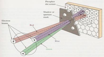
A CRT (Cathode Ray Tube) is made of red, blue and green phosphor dots with corresponding electron beams. Each beam should only strike its respective coloured phosphors. This is accomplished by passing the beams through a shadow mask, or sometimes referred to as the aperture mask. The shadow mask prevents the red beam from spilling over onto an adjacent blue or green phosphor dot. A typical CRT has over 200,000 holes in the shadow mask. To make the three beams converge correctly on their corresponding phosphor dots across the entire face of the CRT requires special modification to the horizontal and vertical deflection mechanisms. Typically, this is accomplished by a set of ring magnets around the yoke.
What Does Bad Static Convergence Look Like?
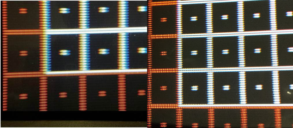
Here is a side-by-side comparison between a pattern generated by the 240p Test Suite and a close up picture of my PVM1944Q. The expected pattern is a white grid surrounded by a red grid (on the right, the example is a perfect screenshot from an emulator). On the left, the pattern displayed on my PVM1944Q shows the blue electron gun out of alignment.
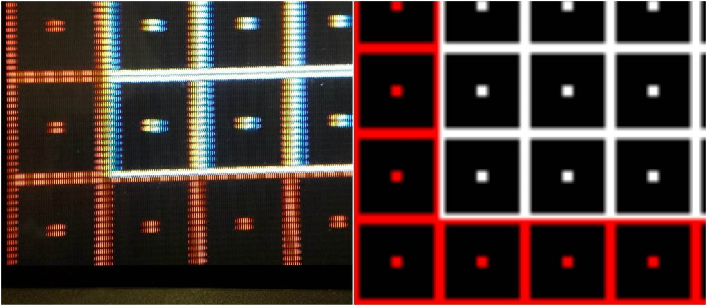
Remember that white on a CRT is generated by a combination of red, green and blue light simultaneously on one point. Therefore a white grid (as generated by 240p Test Suite) is very well-suited to test convergence among other things. Where the red and green beams align, the grid appears yellow. Where all three beams align, the grid appears white. Where no alignment exists, only the individual colours can be seen.
Convergence Rings
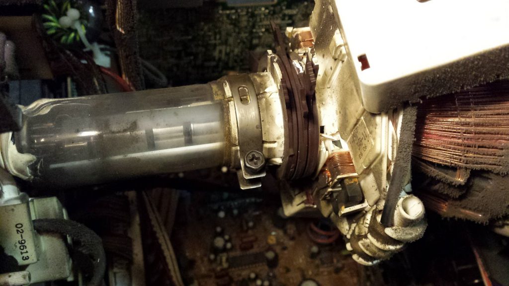
My PVM, and most CRTs, have a set of magnetised rings on the electron tube designed to deflect the electron beams to help adjust convergence. These adjustments rings usually have tabs on them to help with manipulation during the calibration process. The rings on your CRT may be held in place by a small amount of glue, a relic of its original factory calibration; if so you will need to break the rings free from the glue before any adjustments are made. It’s also a good idea to make a line across all rings using a sharpie to mark their current positions (I didn’t do this and boy did I regret it!) – this way you’ll at least to be able to get the rings back to their original state if you get discouraged while attempting this calibration.

Below is my very dirty (don’t worry I cleaned it after) PVM1944Q with its 6 convergence rings on the electron tube.
What is the function of each ring?
The three sets of rings control 3 different parameters. Start from closest to the CRT’s face:
- Set 1 – Purity
- These rings control the purity. My research on these tells me that this very likely does not need to be adjusted after the factory. Nevertheless, purity controls the evenness of colour balance across the entire face of the CRT. I have found, to determine if your purity is correct, simply bring up a full red screen and adjust the first set of rings until the colour balance is uniform throughout the screen.
- Set 2 – Red vs. Blue
- These rings converge Red and Blue at the centre of the screen.
- Set 3 – Green vs. Magenta (Red + Blue)
- Same concept as Set 2, except that these rings now converge Green and Magenta at the centre of the screen.
Adjusting the Rings
There are two methods to adjusting the rings, and quite frankly, this is the hardest thing to adapt to. Each ring set can be rotated either simultaneously or independently (i.e. separated).
Simultaneous Rotation
I found that simply grabbing either ring’s tab in a set and rotating caused both rings to rotate simultaneously and thus maintain a constant angle between the two ring’s tabs. Your rings may not be so tightly bound so I definitely suggest keeping an eye on both tabs to ensure they are moving together.
Effect
Literature I have found online seems to indicate that rotating the rings moves the electron beam vertically though I found this movement to be much more complex. The rotation of a set of rings causes the corresponding colours (refer to Set 2 and Set 3 above) to rotate about the centre of the screen in circles. Depending on the angle between the two rings in a set, continuing to rotate a set of rings may or may not cause the two coloured beams to converge.
Pro-tip: Rotate slowly and look at your results on screen. If you find that no rotational position causes the beams to converge you will need to independently rotate a ring.
Independent Rotation
On my PVM1944Q, to achieve independent rotation, and thus to change the angle between the two ring’s tab, I found that I had to physically restrict one ring from rotating while I rotated the other.
Effect
Literature I have found online seems to indicate that separating the rings (independently rotate on ring from the other) causes the beams to move horizontally though again I found this movement to be much more complex. Where the simultaneous rotation caused the beams to move in small circles around a point, the separation changed the diameter of the circle and thus the intensity of the simultaneous rotation’s effect.
Pro-tip: Try simultaneous rotation first, if no rotation position results in good convergence, separate the rings very slightly (i.e. 5 to 10 degress) and try simultaneous rotation again.
Greediness
The most difficult part of doing this calibration, for me, was to control my greediness. On several occasions I was extremely close to having very good beam alignment only to completely mess it up in the following minutes because I thought I could do better. Hours later I was finally back at the same “extremely close” alignment and I decided it was good enough. Don’t be too greedy. The non-linear effect of the rings’ rotation makes this a very difficult calibration.
Results
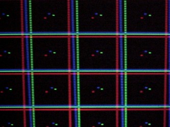
After much frustration, and several greediness setbacks, I was finally able to get the convergence to a “good enough” setting. I say this because I am beginning to feel like this is about as best as my PVM will ever look and I should be satisfied with this setting because it’s much better than what it used to be. Keep in mind that the two comparison pictures below were taken several days apart – I did toy with this calibration for many nights before accepting this result as final.
Conclusion
Is the image quality better?
Absolutely, just look at the comparison picture above. While not perfect, the RGB beams are much better aligned now producing a better image – especially at the corners of the screen. There are still some places where I can see the Blue beam slightly offset but generally this setting is a compromise for the entire screen. Overall, this is probably the best it will look.
Things to do differently?
I really regret not marking the original position of the rings using a sharpie. At several points I got really frustrated and would’ve really liked to be able to bring all the rings back to their starting point. Don’t be like me!
Is it worth it?
Yes.