This is a guest post from fluxcore that details how to improve audio from your NES/Famicom and make them sound closer to the proper audio the original Famicom outputs…
Obtaining decent audio output from the Famicom and NES systems has always been an issue – the original, ‘reference’ console, the Famicom (model HVC-001), only provides RF output as standard, requiring a modification to get any kind of decent quality audio out, and even then has a large amount of background noise. The western NES systems don’t retain the cartridge expansion audio capability, instead redirecting the mixing to the expansion port on the bottom of the console, resulting in all Japanese cartridges, including the Famicom Disk System, having incomplete sound even when using cartridge converters. Without mods, there is no way for the NES to pass on the audio from the cartridge slot to the audio amp.
Further complicating matters, later HVC-001 Famicom revisions (HVC-CPU-GPM-01 and HVC-CPU-GPM-02, with the “FF” logo on the front) have their internal audio volume drastically altered by reducing the gain of the on-board amplifier while the redesigned model, the HVC-101, commonly known as the “AV” or “New” Famicom, sports a completely different audio circuit design. Both of these result in expansion audio mixing that is far too loud compared to prior revisions.
Stock AV Famicom HVC-101: https://soundcloud.
While some later carts (notably Gimmick) may potentially have been created with this newer mixing circuit in mind, it’s not definitely clear which mixing method actually sounds better in those cases. Regardless, the vast majority of carts with expansion audio are clearly made for the HVC-001 circuit.
Potential mods for restoring the original mix have been explored in forums for many years, but none were ever considered ‘complete’ – most resulting in an overdriven and distorted signal in an attempt to raise the CPU audio up to the level of the expansion audio. A more thoroughly bypassed mod is required.
Master audio circuit modder Ace (https://twitter.com/
The drums and synths are back in balance, allowing the instrumentation to be heard in full. Before, the AV Famicom was an excellent choice for cartridges without expansion sound – now it also excels with them.Assuming you have an NESRGB and stock AV Famicom handy, here are the instructions to follow for Ace’s audio restoration mod:
* Parts Needed
** NESRGB board (pre-installed)
** 2x wires ~5 inches (13cm)
** 1x shielded wire ~9 inches (23cm)
** 0603 1% 15K Ohm SMD resistor
** 0603 1% 20K Ohm SMD resistor
** 0603 1% 100K Ohm SMD resistor
** 1uF electrolytic capacitor (can use an X7R 0603 SMD capacitor if preferred). 50V 20% is fine.
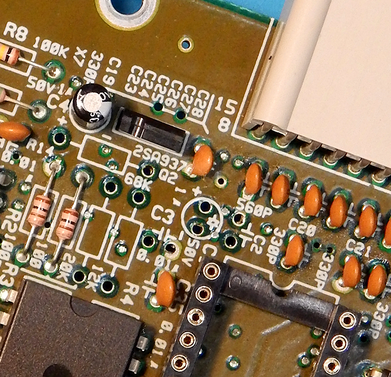
* AV Famicom main board modifications
Several resistors and capacitors need to be removed from the AV Famicom’s main PCB. You will need to remove the NESRGB board to access them. These are:
** Resistor R3 (20K Ohm) – red rectangle
** Resistor R4 (12K Ohm) – cyan rectangle
** Resistor R14 (68K Ohm) – purple rectangle
** Capacitor C1
** Capacitor C2 (330pF) – blue square
** Capacitor C3 (0.01uF) – yellow square

After removal:
Pin 17 of the IC at U3 – ‘BU3266S’ must be lifted, see centre of photo below:

Then, pins 15 and 16 of the BU3266S should be bridged on the underside of the board. This will tie the now unused audio input on pin 16 to ground so as to prevent it from floating.
Now, two wires need to be soldered to CPU pins 1 and 2, these will be joined to the ‘A’ and ‘B’ pads on the NESRGB, respectively. I recommend routing these wires down through the gap in the RF shielding by the controller ports.

Finally, a shielded cable needs to be added from cartridge connector pin 45 to NESRGB pad ‘O’. The cable’s shield can be connected to any ground nearby, I like cartridge connector pin 16. Route this cable up through the gap in the RF shield next to the AV port. The other end of the shielding should be soldered to the ‘GND’ pad on the NESRGB, next to the ‘B’ pad.

* NESRGB board modifications
2 components need to be completely removed, 4 replaced, and 3 bridged. Unfortunately there are no silk screen markings for these components, so a textual description is difficult. See the image below – remove the components marked with a red rectangle, remove and bridge the components marked with a yellow rectangle, and remove + replace the components in the purple rectangles with the value written within the rectangle.

If using an electrolytic capacitor, be very careful with how the legs are bent – they must not touch, but also must not put much lifting force on the pcb pads (which are very small and can easily be damaged by such a large component).
After component removal:

After bridges, new components, and wires added (i.e. mod complete):

Enjoy your AV Famicom restored audio mix experience!
In addition, it is recommended to replace R125 by a 20K resistor as Sharp erroneously installed a 22K resistor in this spot.